
What Is Normal O2 Sensor Voltage At Idle? Answered
So, here are the details about Normal O2 Sensor Voltage At Idle. The oxygen (O2) sensor functions as a small voltage generator. It generates a voltage between 0.01 and 0.98 volts in theory. Depending on how much oxygen is in the exhaust, it does this. The ECM uses this signal as one of its main inputs to regulate the air-fuel mixture and emissions.
Table of Contents
Normal O2 Sensor Voltage At Idle
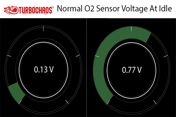
The output voltage of a healthy oxygen sensor will exhibit fast fluctuations between 0.1 and 1.0 volts.
The O2 sensor measures the oxygen content of the exhaust. The O2 sensor’s ability to sense is achieved by producing a small voltage proportional to the oxygen level of the exhaust.
To put it another way, a low oxygen content results in a high voltage (0.90 Volts – Rich mixture), while a high oxygen content results in a low voltage (0.10 Volts – Lean mixture).
The O2 sensor should theoretically cycle between 0.00 and 1.00 volts; however, in practice, it only cycles between 0.10 and 0.90 volts. In many contemporary vehicles, the AFR or Wideband sensor has replaced the O2 sensor. However, the after-cat or rear O2 sensor is still the same conventional O2 sensor.
How Does An Oxygen Sensor Work?
When it gets hot, the O2 sensor behaves like a tiny generator and generates its voltage. Inside the sensor’s vented lid at the end that fastens to the exhaust manifold is a zirconium ceramic bulb. The exterior of the bulb is covered in a porous platinum coating. Two platinum strips are used as electrodes or connections inside the light bulb.
While the bulb’s interior is vented internally through the sensor body to the outside atmosphere, the exterior of the bulb is exposed to the hot gases in the exhaust.
While modern design O2 sensors “breathe” through their wire connectors and have no vent hole, older-style O2 sensors have a small hole in the body shell where air can enter the sensor.
It isn’t easy to believe, but there is just enough area for air to seep into the sensor between the insulation and the wire (for this reason, oil should never be used on O2 sensor connectors since it can obstruct airflow). Inside the sensor’s vented lid at the end that fastens to the exhaust manifold is a zirconium ceramic bulb.
The ceramic bulb in the sensor receives voltage due to the difference in oxygen content between the exhaust and ambient air. The voltage reading increases as the difference grows.
When minimal unburned oxygen is in the exhaust, and the fuel mixture is rich, an oxygen sensor will normally produce up to roughly 0.9 volts. When the combination is lean, the sensor output voltage will fall to 0.2 volts or less. When the air-to-fuel ratio is just right, at around 14.71 to 1, the sensor will register a voltage of about.45 volts.
The computer leans the fuel mixture to lower the sensor’s feedback voltage in response to a rich signal from the O2 sensor. The computer reverses again, causing the fuel mixture to become rich when the O2 sensor reading becomes lean (low voltage).
Depending on the fuel system, the fuel mixture constantly flip-flops back and forth at varying speeds. The changeover rate is the slowest on engines with feedback carburetors, usually happening once per second at 2500 rpm. While multiport injection engines are the fastest, throttle body injection engines are somewhat faster (2 to 3 times per second at 2500 rpm).
Many oxygen sensors contain a small heating element inside to help them achieve operational temperature more rapidly since the oxygen sensor needs to be hot (600 degrees or more) before it creates a voltage signal. Additionally, the heating element can prevent the sensor from overheating during extended idle, forcing the system to return to an open loop.
Testing O2 sensors
When testing O2 sensors, these easy actions should be taken.
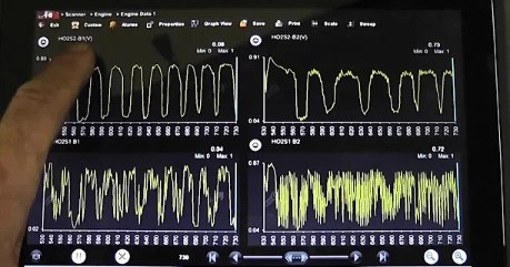
- Check the car for any O2 sensor codes and examine the PID of the data stream. Normal O2 sensor voltage cycling should have the correct amplitude and frequency. An open O2 circuit or a lack of an O2 sensor (dedicated) ground are signs of an O2 sensor trapped at a fixed bias voltage. Evaluate the O2 sensor data with a graphing multi-meter to spot potential issues.
- As you read the scan data, open the throttle and look for the minimum and maximum values of the oxygen sensor (0.1 to 0.9 volts). This is a preliminary sign of proper operation, even though it is not conclusive proof of proper O2 sensor operation.
- Some automakers use a special ground wire for the O2 sensor grounded at the engine block or chassis. The O2 sensor will be worthless if this ground wire is lost or damaged. Only the O2 sensor circuit of the ECM is fed by this ground wire. This O2 sensor circuit does not get power from the main engine ground.
- Check the integrity of the O2 sensor wire. Most O2 sensors are biased, and an open signal line will read the bias voltage, whatever it may be. A consistent reading of 2 or 4 volts on a Chrysler indicates an open circuit because later-model Jeep/Chrysler O2 circuits are frequently biased at these levels. The ECM will frequently set an “O2 sensor High Voltage” code under these circumstances.
- Lastly, use a scope or graphing multi-meter to confirm that the O2 sensor is operating correctly. Make sure the frequency and amplitude are correct. Remember that the O2 sensor readings from scanners are interpretive values and might not correspond to the actual voltage reading. This is the rationale for performing the last manual test.
How Does A Downstream O2 Sensor Monitor Converter Efficiency?
Like an upstream O2 sensor in the exhaust manifold, a downstream oxygen sensor is located in or after the catalytic converter. The sensor produces a voltage that varies as the amount of unprocessed oxygen in the exhaust does.
When the fuel mixture is low (there is more oxygen in the exhaust), the voltage output of a typical zirconia-type O2 sensor falls to roughly 0.2 volts. The sensor’s output increases to roughly 0.9 volts when the fuel mixture is rich (less oxygen in the exhaust). The PCM is informed by the high or low voltage signal whether the fuel mixture is lean or rich.
A new type of Wide Ratio Air Fuel (WRAF) Sensor is utilized in some contemporary automobiles. The signal changes in direct proportion to the amount of oxygen in the exhaust rather than providing a high or low-voltage signal. This offers a more accurate measurement for improved fuel management. Because they can sense extremely lean air/fuel mixes, these are also known as wideband oxygen sensors.
By contrasting the outputs from the upstream and downstream oxygen sensors, the OBD II system tracks converter efficiency. The downstream oxygen sensor should exhibit little activity (few lean-to-rich transitions, often known as cross counts) if the converter performs its job and lowers the exhaust contaminants. The voltage reading from the sensor should also be at least 0.45 volts on average and fairly stable (not fluctuating up or down).
The converter is no longer cleaning up the pollutants in the exhaust if the signal from the downstream oxygen sensor begins to coincide with the signal from the oxygen sensor(s) upstream.
When emissions are predicted to exceed federal limitations by 1.5 times, a diagnostic trouble code is set, and the Malfunction Indicator Lamp is turned on. For additional information on converter issues, see Troubleshooting a P0420 Catalyst Code.
The PCM will activate the Malfunction Indicator Lamp (MIL) and assign a diagnostic fault code if converter efficiency has decreased to the point where the car exceeds the pollution limit. The failed converter may then require a further diagnosis to be confirmed.
The converter must be rebuilt to restore emissions compliance if the upstream and downstream O2 sensors work properly and show reduced converter efficiency. The car won’t pass an OBD II emissions test if the PCM contains any converter codes.
What’s The Difference Between A Heated And Unheated Oxygen Sensor?
The internal heater circuit of heated oxygen sensors allows them to reach operating temperature more quickly than unheated sensors. A heated oxygen sensor (between 600 and 650 degrees F) is required to produce a voltage signal.
An O2 sensor can be heated up to operating temperature by the hot exhaust from the engine. Still, it may take several minutes, depending on the ambient temperature, engine load, and speed.
The fuel feedback control system continues to operate in an “open loop” during this time and does not modify the fuel mixture using the signal from the oxygen sensor. A rich fuel mixture, wasted fuel, and greater emissions are typical outcomes.
To route voltage via the heater, an internal heater circuit must be added to the oxygen sensor as soon as the engine starts to warm up the sensor. A resistor serves as the heating element; when current flows through it, the resistor glows red hot.
Depending on the sensor, the heater will raise the sensor’s operational temperature in 20 to 60 seconds. The heater will also maintain the sensor’s heat even if the engine is idle for an extended time.
Two, three, or four wires are frequently used in heated O2 sensors (the additional wires are for the heater circuit). Note: Replacement O2 sensors must have the same internal resistance and number of wires as the original sensors.
The OBD II system likewise monitors the heater circuit; if it malfunctions, a trouble code will be set. Since the heater is a sensor component and cannot be changed separately, the O2 sensor must be changed if the heater circuit is open or shorted, and the issue is not with the external wiring or sensor connector.
Conclusion
Here we conclude all about Normal O2 Sensor Voltage At Idle. The exhaust manifold has an oxygen sensor installed so exhaust gases can flow across its working surface. The oxygen sensor is a galvanic current source that adjusts its output voltage based on the temperature and oxygen concentration of the surrounding air.
An output signal differs based on the oxygen content of the exhaust gases. The sort of material the sensor is constructed of affects the shape of this signal. The oxygen sensor thus reports the amount of oxygen in exhaust gases to the onboard controller.
The signal’s clock edge between its “high” and “low” states is insignificant and can be disregarded. The onboard controller receives a signal from the oxygen sensor, evaluates it against a value stored in memory, and modifies the fuel injection duration in both directions if the signal deviates from the optimal value for the mode. Thus, a maximum fuel economy and a minimum amount of hazardous gases are obtained through the implementation of feedback and the appropriate operating mode.
Frequently Asked Questions
What is the steady voltage for the O2 sensor?
The downstream O2 sensor will settle down and “flat-line” at a consistent voltage measurement, often around 0.45 volts or so, as soon as the converter turns off.
What is a normal oxygen sensor?
95% or more oxygen is considered to be a normal level. 90% of patients with sleep apnea or chronic lung illness may have normal levels. The SpO2 value on a pulse oximeter displays the blood’s oxygen content as a percentage. Call your healthcare practitioner if the SpO2 level you take at home is less than 95%.
Is high O2 sensor voltage rich or lean?
O2 sensors from the first generation serve as a short rich/lean indicator switch. The O2 sensor produces a “high” voltage signal of 600 to 1000 millivolts when the A/F mixture operates richly and a signal of 300 millivolts or less when the A/F mixture is lean.
Why is my O2 sensor voltage low?
The downstream oxygen sensor should typically generate a constant voltage of roughly 450 mV. And if it’s lower, either the sensor circuit is malfunctioning, or there is too much oxygen in the exhaust stream. Several potential causes include bad wiring, high resistance, or even a defective sensor.

Welcome to the exhilarating world of Matt Rex, a professional car racer turned renowned vehicle enthusiast. Immerse yourself in his captivating blog as he shares heart-pounding adventures, expert reviews, and valuable insights on cars, trucks, jets, and more. Fuel your passion for speed and discover the beauty of vehicles through Matt’s engaging stories and meticulous expertise. Join the ever-growing community of enthusiasts who find inspiration and expert advice in Matt Rex’s blog—a digital hub where the thrill of speed meets the pursuit of knowledge.


![68RFE Transmission Operating Temperature [Answered]](https://www.turbochaos.com/wp-content/uploads/2023/12/68RFE-Transmission-Operating-Temperature-768x617.jpg)